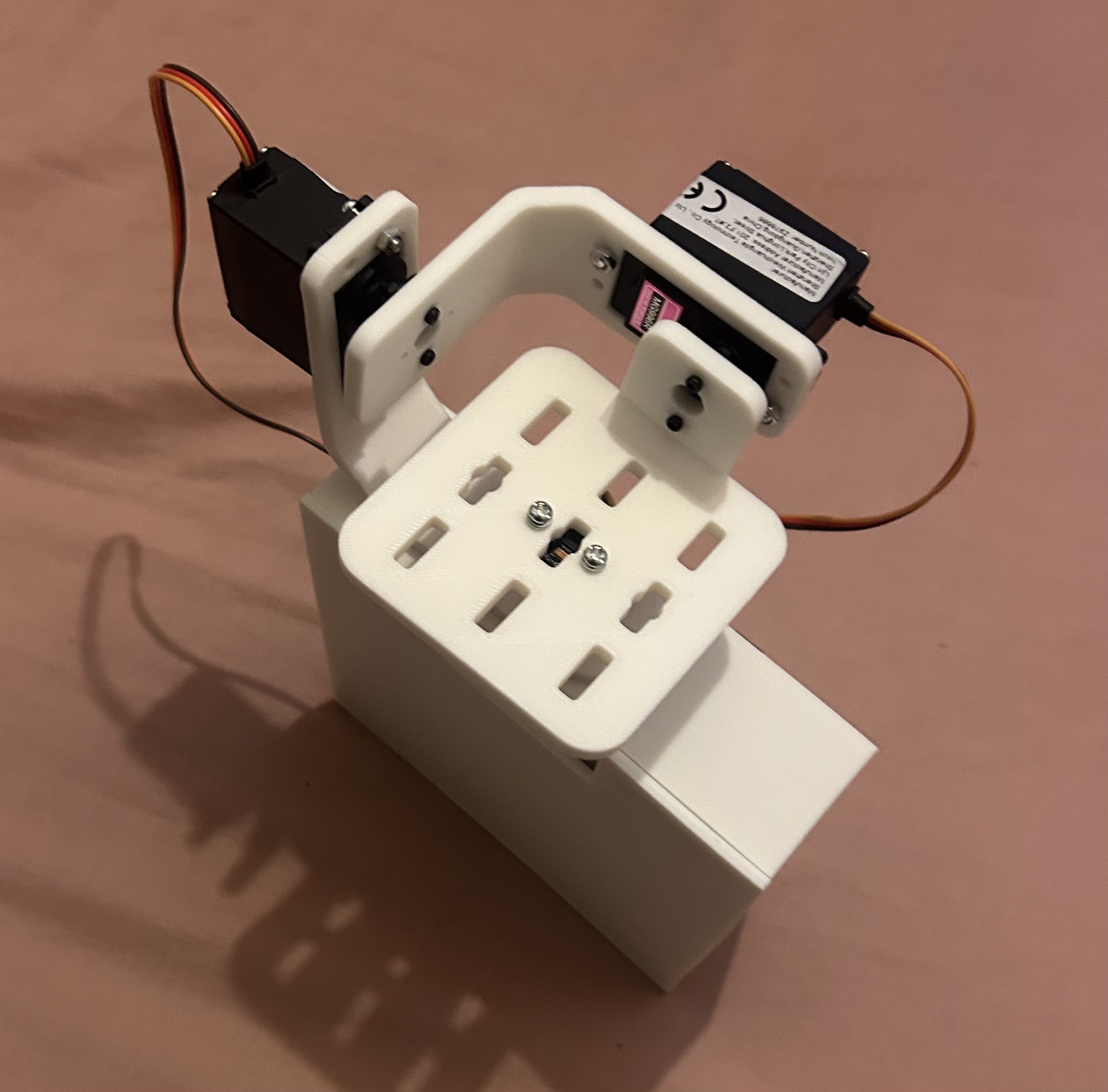
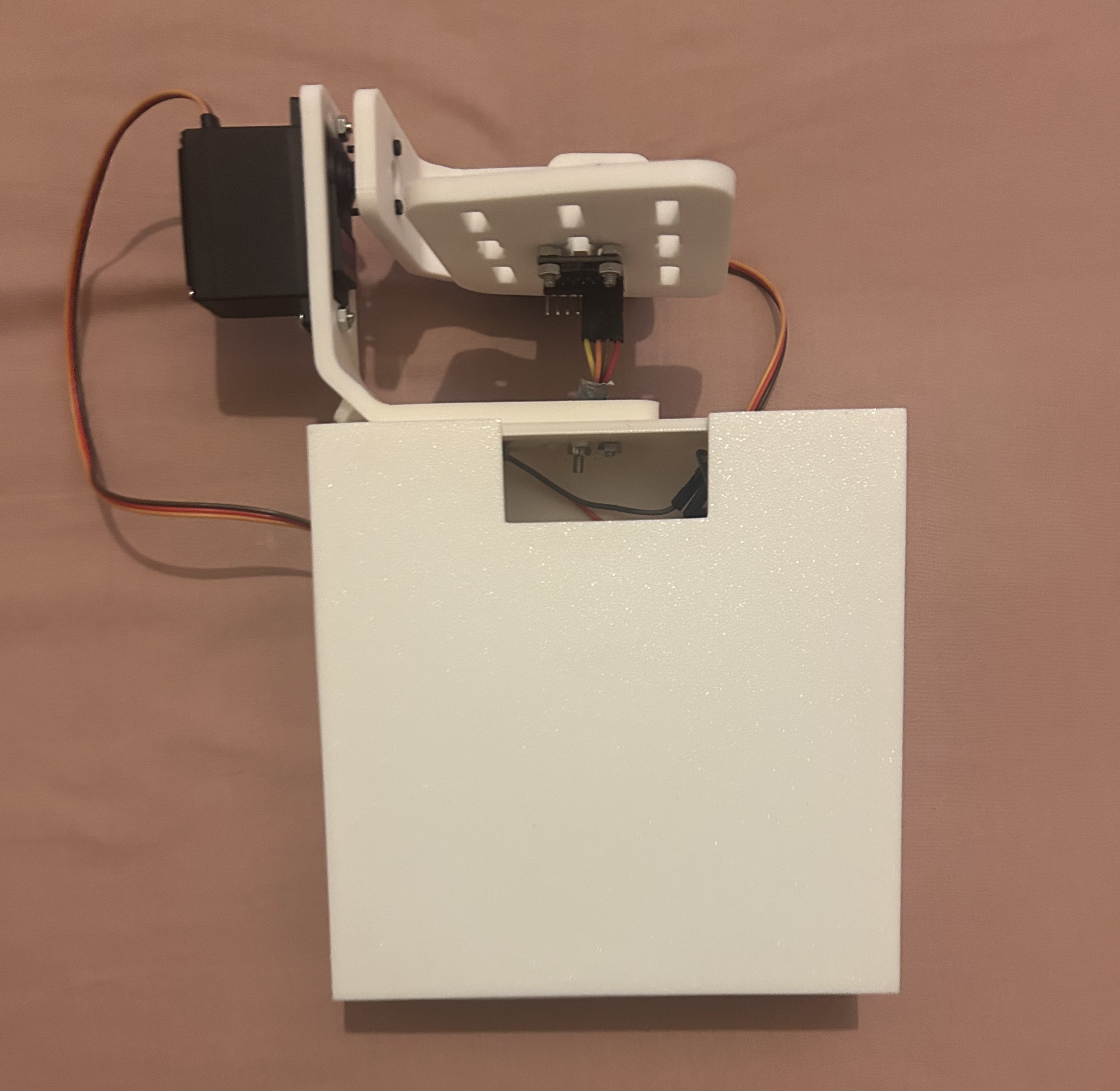
Removable hardware
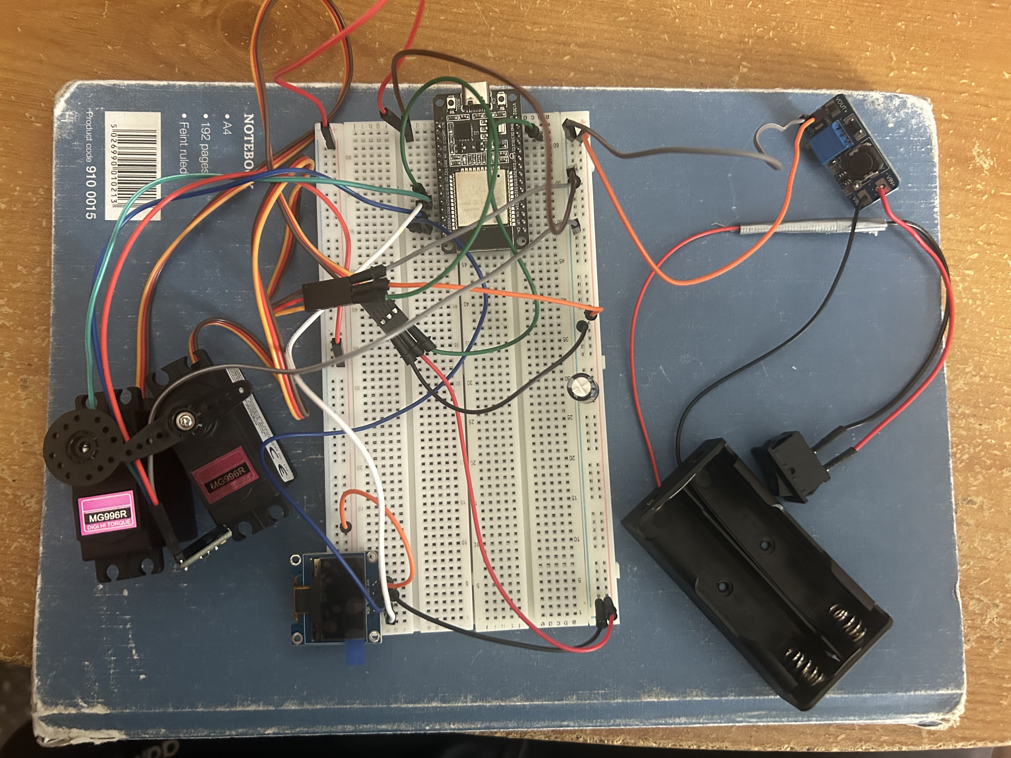
Socketed ESP32, detachable IMU and mechanically secured PCB enabled disassembly without destroying components.
MECHATRONICS / CONTROL SYSTEMS · INDEPENDENT HARDWARE PROJECT
A two-axis stabilisation demonstrator integrating an MPU6050 inertial sensor, ESP32 firmware, complementary filtering, PID control, MG996R servos, a custom two-layer KiCad PCB and a modified 3D-printed Fusion 360 frame.
01 / PROJECT BRIEF
The objective was to keep a moving platform approximately level by estimating its roll and pitch, calculating corrective commands and driving two servo axes. The design combined control software with a physical structure, electrical power distribution and a browser-based monitoring interface.
Scope: This is a working limited-angle engineering demonstrator, not a precision-stabilised or wide-range commercial gimbal. The reported ±5° figure refers to restricted servo motion, not measured platform attitude accuracy.
02 / CLOSED-LOOP CONTROL
An MPU6050 mounted on the moving platform provides accelerometer and gyroscope readings. The ESP32 uses both measurements to estimate attitude, compares it with the requested target and commands roll/pitch correction through two MG996R servos.
Acquire MPU6050 accelerometer and gyroscope values over I²C.
Combine integrated gyro rate and accelerometer attitude using a complementary filter.
Calculate roll/pitch error and proportional-derivative correction, with integral gain at zero.
Apply correction around calibrated servo neutral positions within constrained travel.
Controller gains were adjusted for the assembled prototype, not identified from a measured dynamic model. The filter reduces gyroscope drift while retaining short-term gyro responsiveness; it cannot correct mechanical backlash or insufficient servo supply current.
03 / ELECTRICAL & PCB DESIGN
A compact two-layer KiCad board replaced the breadboard wiring, with socketed ESP32 headers, servo connectors, a remote MPU6050 connector, labelled power input and mounting holes. The carrier approach kept the major modules removable for testing and reuse.
| Item | Design / connection | Engineering purpose |
|---|---|---|
| ESP32 Dev Board | Socketed headers; USB-powered controller | Firmware, servo commands and Wi-Fi dashboard |
| MPU6050 | I²C SDA GPIO 21, SCL GPIO 22; remote 4-pin connection | Measures orientation of the moving platform rather than fixed base |
| MG996R ×2 | Roll signal GPIO 13; pitch GPIO 19 | Independent axis actuation; GPIO 19 replaced bootstrap-related GPIO 12 |
| Servo supply | 18650 batteries in parallel → MT3608 boost → external 5 V rail | Avoids drawing servo current from the ESP32 logic supply |
| Bulk / local capacitors | 1000 µF on servo rail; 100 nF local decoupling | Supports transient rail behaviour; does not guarantee current capacity |
| PCB routing | 1.0 mm 5 V/GND; 0.4 mm 3.3 V; 0.3 mm signal traces | Wider current-carrying paths than the control signals |
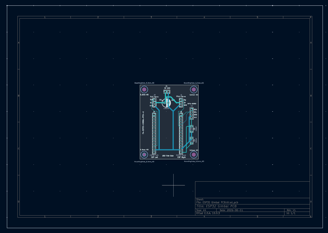
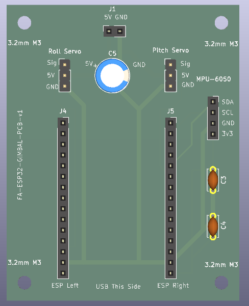
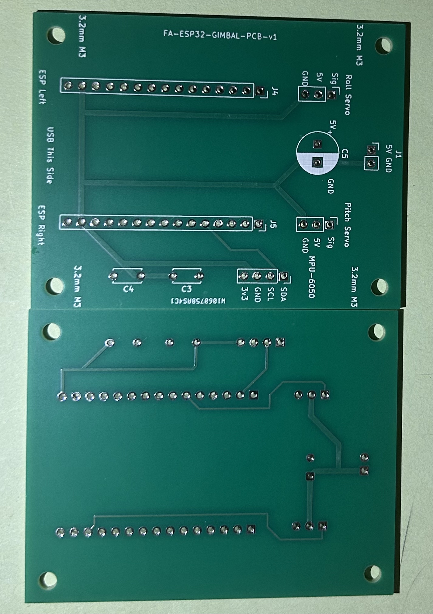
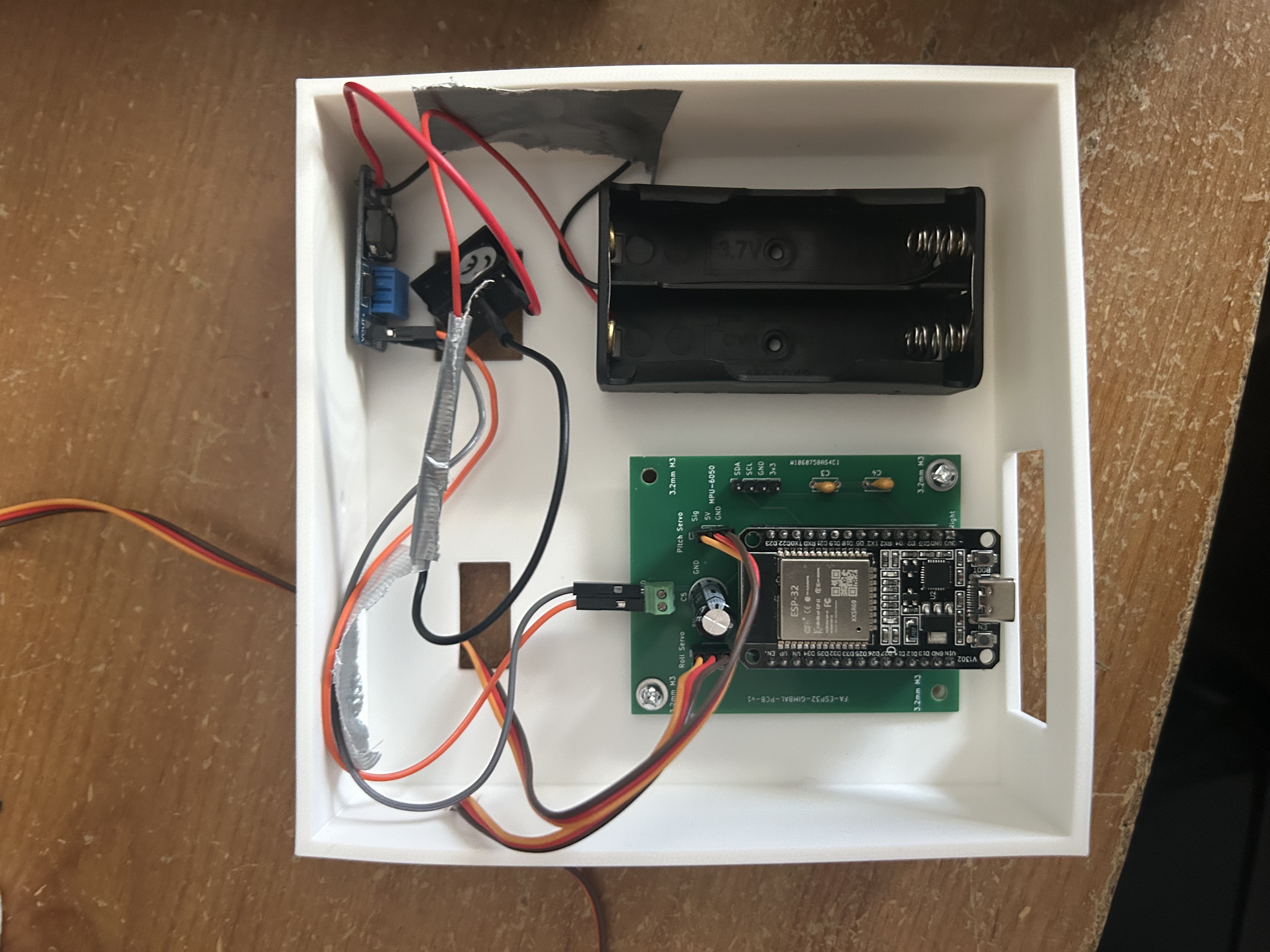
Power limitation: Large or abrupt servo movements produced unstable behaviour consistent with inadequate transient supply capability. A bulk capacitor and separate rail helped the design, but the demonstration still required small actuation limits. Voltage transient magnitude and peak current were not instrumented.
04 / CAD & MANUFACTURING
The starting bracket and platform geometry was based on the HowToMechatronics self-stabilising platform. I adapted the model for a two-axis ESP32 implementation by removing yaw hardware and designing the electronics box, PCB mounting arrangement, cable cutouts and removable lid.
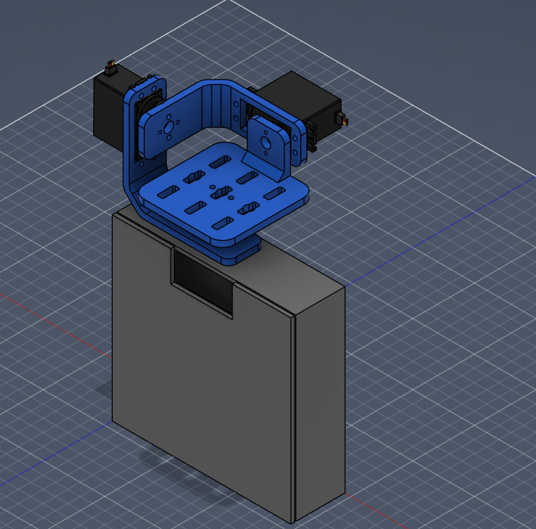
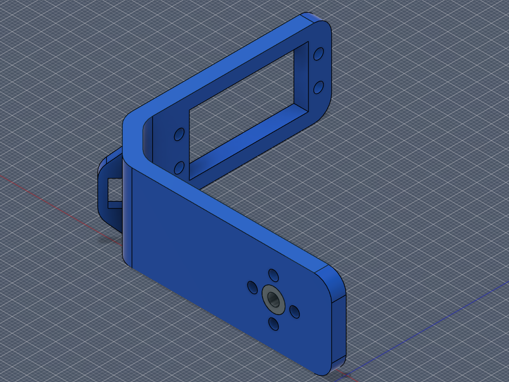
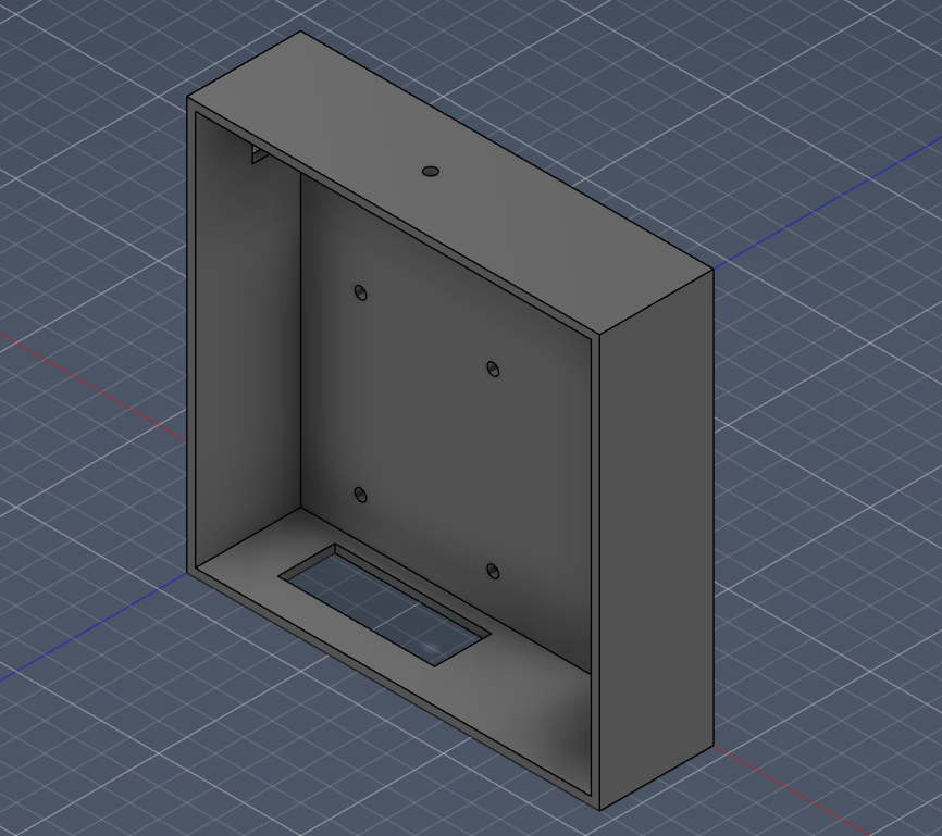
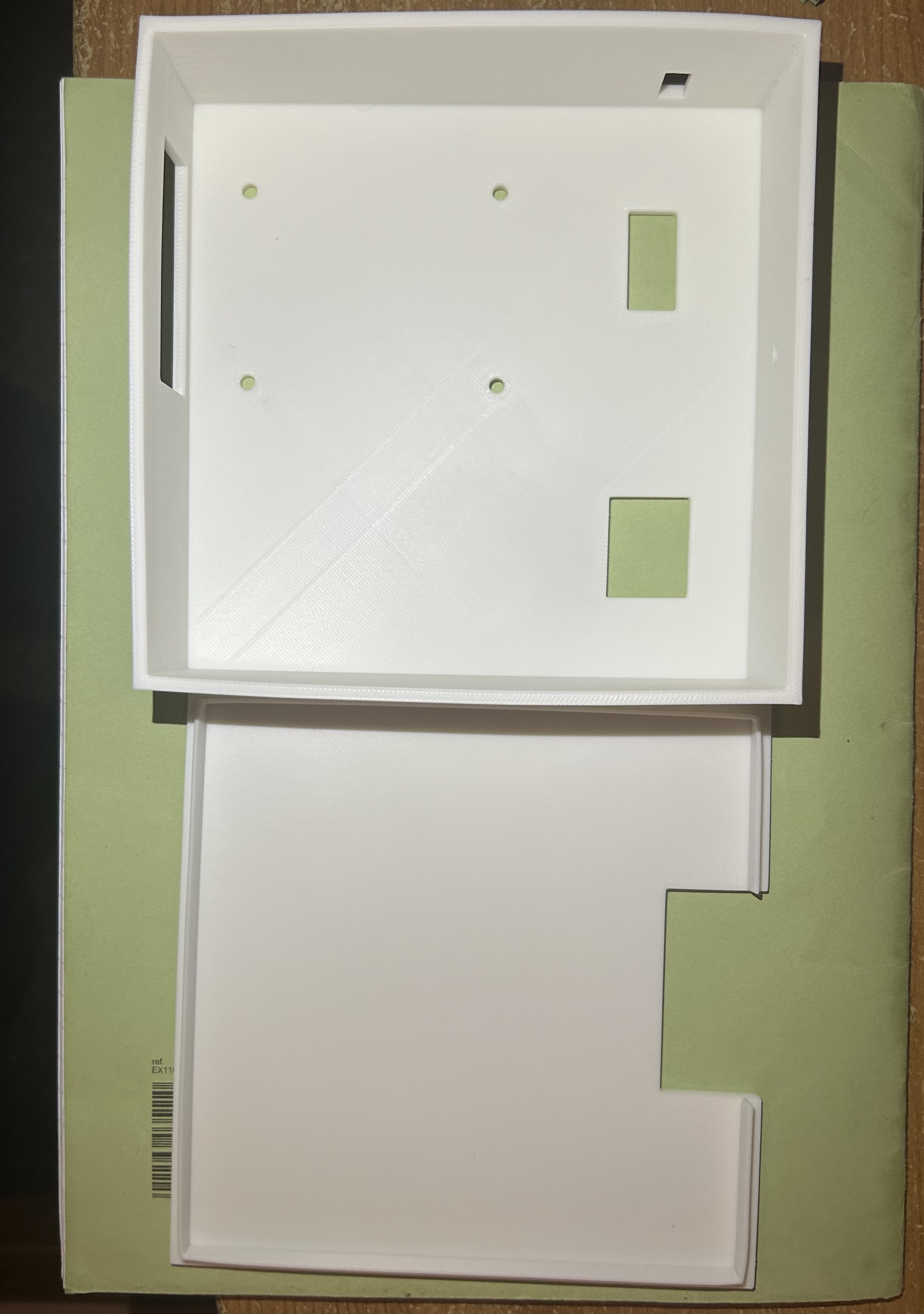
Socketed ESP32, detachable IMU and mechanically secured PCB enabled disassembly without destroying components.
Separate PLA FDM brackets, screw mounting, simple rectangular cutouts and a friction-fit lid reduced complexity.
The sensor attaches to the moving platform so the controller measures the attitude of the element being stabilised.
Printed parts showed flex and slight deformation; static neutral offsets compensated the resting angle but could not eliminate the mechanical compliance.
PCB fabrication and 3D printing received student project manufacturing support from PCBWay. Sponsorship supported fabrication, not a claim of product certification.
05 / FIRMWARE & DASHBOARD
The PlatformIO / Arduino firmware runs the sensor-feedback loop and a local ESP32-hosted web server. The dashboard provides live roll/pitch values, sliders for commanded setpoints, a return-to-level control and a heartbeat that switches the system back to stabilisation if browser updates stop.
/dataRoll and pitch telemetry as JSON/modeToggle stabilisation and manual setpoint control/setpointUpdate desired roll/pitch angles/heartbeatKeep-alive for setpoint mode; revert when absent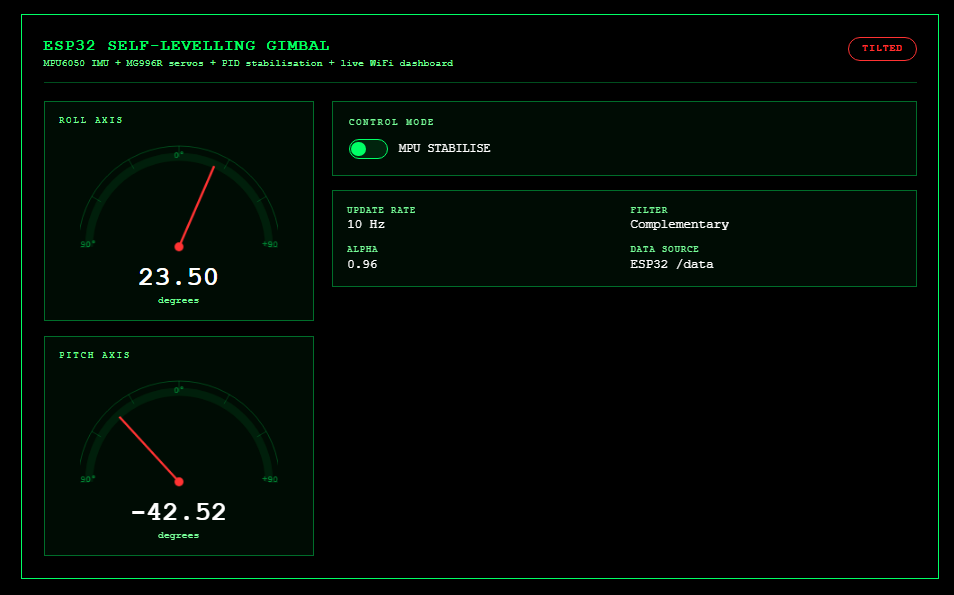
constexpr int ROLL_NEUTRAL = 99;
constexpr int PITCH_NEUTRAL = 85;

constexpr int ROLL_MIN_POSITION = ROLL_NEUTRAL - 5;
constexpr int ROLL_MAX_POSITION = ROLL_NEUTRAL + 5;

constexpr int PITCH_MIN_POSITION = PITCH_NEUTRAL - 5;
constexpr int PITCH_MAX_POSITION = PITCH_NEUTRAL + 5;
Neutral values account for physical resting offsets. The ±5° restriction applies to the servo command around these calibrated positions; it is not an angle-error measurement. The OLED used in early development was omitted from the final physical build.
06 / VALIDATION
Checked basic sensor fusion, servo commands, Wi-Fi interface logic and control modes before powering physical hardware.
Confirmed IMU communication, servo directions, setpoint control and operation using separated controller/servo supplies.
Finished KiCad routing and DRC, ordered the PCB, soldered the board and assembled printed parts and power electronics.
Recorded observable roll/pitch correction and dashboard telemetry with both servo axes restricted to ±5° of command travel around calibrated neutral.
Evidence boundary: Physical photographs, KiCad images, code, design files and a demonstration video support completion of the prototype and limited-angle correction. No traceable settling-time measurements, calibrated angular-accuracy data or recorded supply-transient waveforms are provided. Precision stabilisation and high-disturbance performance are not claimed.
07 / DESIGN LESSONS
The electronics and mechanical structure constrained achievable control performance. Sudden servo movements could exceed the practical power-delivery capability of the battery/boost arrangement, while structural flex and alignment offsets complicated tuning. Restricting actuation produced a demonstrable, repeatable operating condition for the completed project.
Future iteration: Rebuild the hardware, log command and attitude data, independently measure angle response, instrument the 5 V rail during servo transients, improve bracket stiffness and evaluate a higher-current 5–6 V regulator. These are planned experiments, not completed validation.