Proportional control, not full PID
Proportional motor-speed correction provided a simpler controller to tune for the robot's route and intended speed. Integral and derivative terms were not introduced without a demonstrated need.
ROBOTICS / EMBEDDED SOFTWARE · 2025–2026
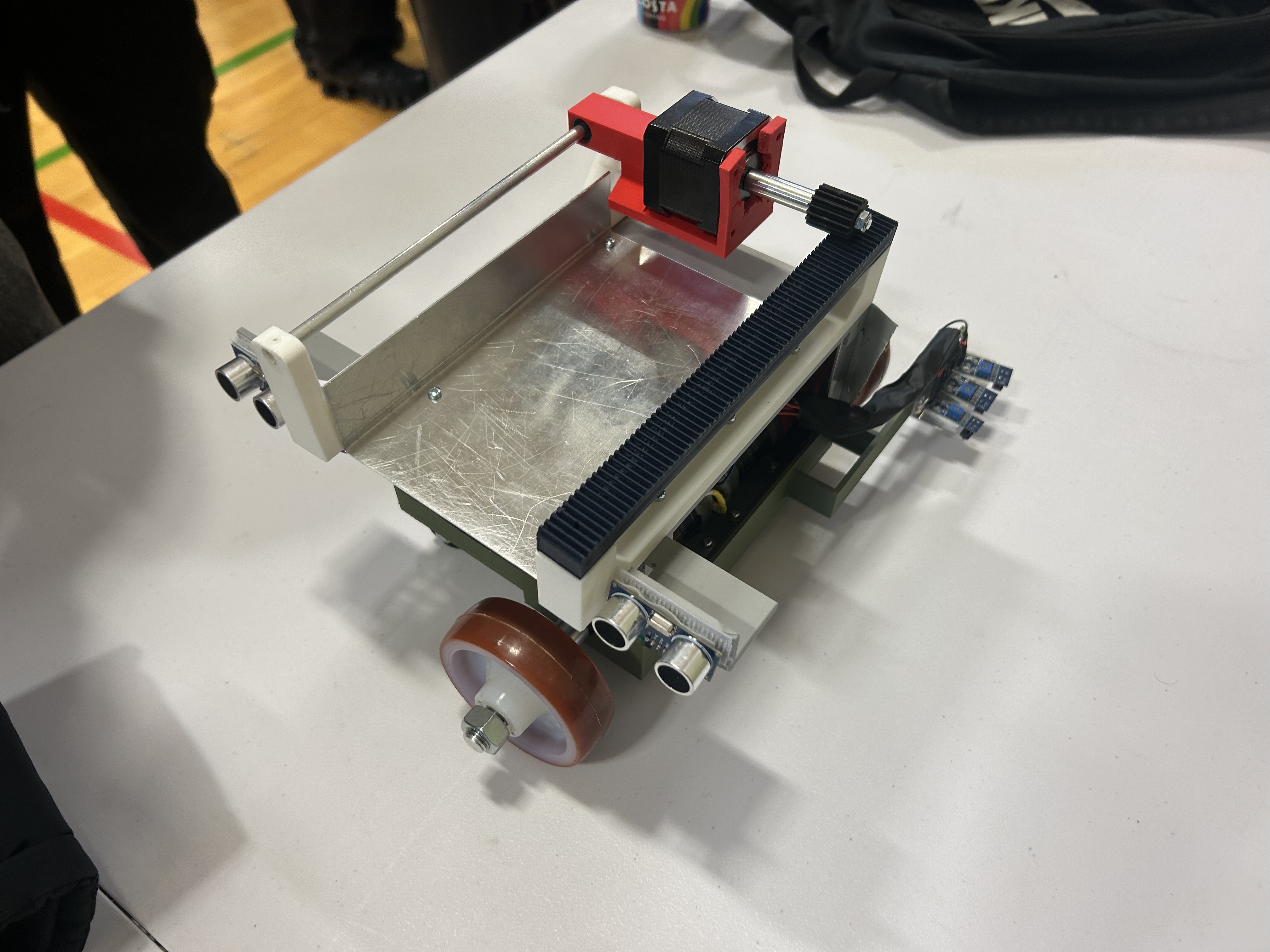
An autonomous line-following robot designed to carry and deliver surgical instruments as a university engineering demonstrator. I was the sole software developer within an eight-person team, responsible for the modular embedded controller, navigation, delivery logic and software-side subsystem testing.
01 / PROJECT BRIEF
The team developed a mobile robot to follow a marked route, detect designated delivery locations and actuate an instrument rack. The concept addressed hospital instrument transport, but the prototype was a university demonstrator, not a clinically validated medical device.
Scope clarification: I wrote the software and prepared subsystem test sketches. Other team members developed the mechanical design, CAD, physical construction and electrical wiring. The complete robot was a team achievement.
02 / CONTROL SYSTEM
The base control layer handles continuous line tracking and recovery. A higher-priority sequence responds to ultrasonic detection of delivery plates and temporarily overrides normal navigation.
Three TCRT5000 IR sensors feed proportional left/right speed correction.
Directional memory guides recovery when the marked line is temporarily lost.
Front ultrasonic sensor rising-edge detection begins the approach sequence.
Rear sensor rising-edge detection initiates stepper-driven rack movement.
The firmware also uses a post-delivery cooldown to reduce duplicate triggering. It checks for a newly detected plate rather than treating every sample within detection range as a new event.
03 / ENGINEERING DECISIONS
Proportional motor-speed correction provided a simpler controller to tune for the robot's route and intended speed. Integral and derivative terms were not introduced without a demonstrated need.
Sequential sensor reads simplified debugging and integration. The project did not establish measured interrupt-latency or deterministic timing advantages.
Previous and current readings were compared to prevent a stationary plate from triggering repeated deliveries; the firmware also included a 2,000 ms cooldown.
Motor control, sensor acquisition, finite-state control and configuration were split into modules, allowing individual tests without rewriting navigation logic.
Simulation mode injected predefined sensor inputs and substituted Serial output for physical motor commands so state transitions could be exercised before full hardware integration.
Pin assignments and tuning parameters were stored centrally, including base motor speed, ultrasonic distance threshold, plate-event timeout and delivery cooldown.
04 / HARDWARE
| Component | Role | Engineering rationale |
|---|---|---|
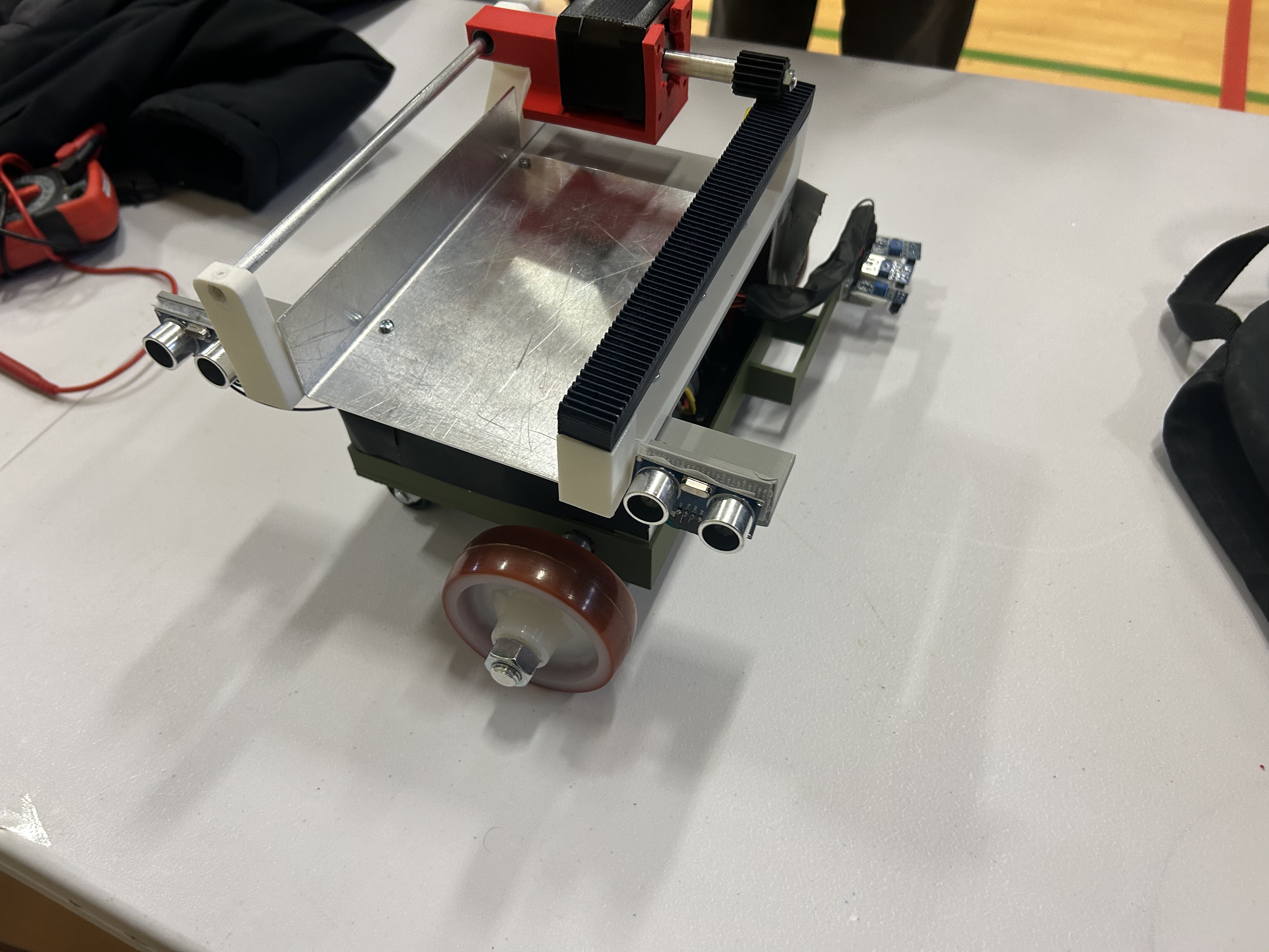
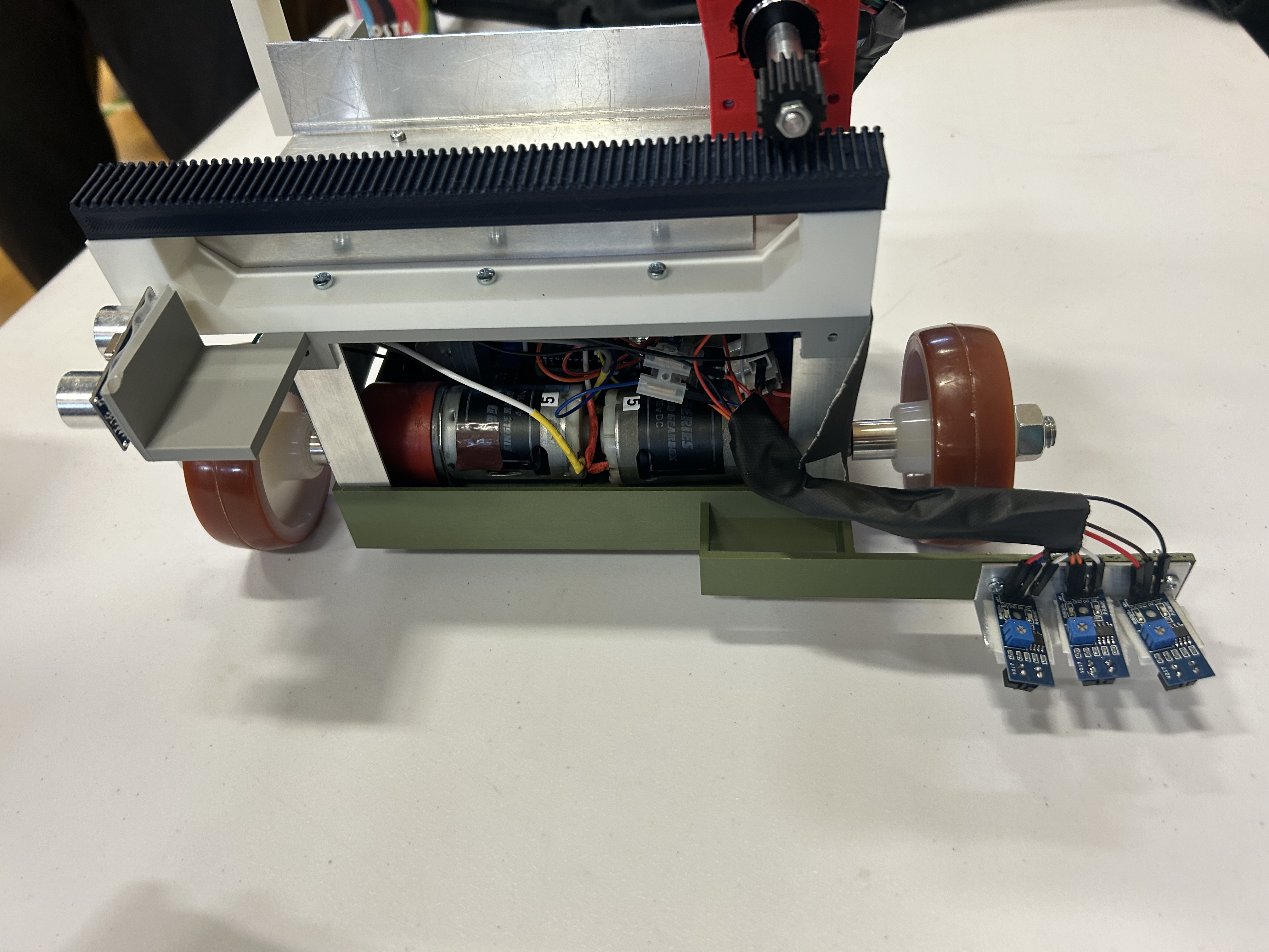
| Arduino Uno Rev 3 | Main controller | Adequate I/O and existing Arduino toolchain within budget |
| L298N dual H-bridge | DC motor drive | Independent left/right speed and direction control |
| 3 × TCRT5000 IR | Line tracking | Low-cost reflectance-based route sensing |
| 2 × HC-SR04 | Delivery location detection | Front/rear event sequence for triggering rack operation |
| Stepper motor + A4988-based driver | Instrument rack actuation | Discrete stepping of the delivery mechanism |
| 11.1 V (3S) Li-ion + DC-DC converter | System power | Battery supply with regulation for subsystem voltage requirements |
05 / SOFTWARE
The source project separates the main state machine, configuration, type definitions, sensor interfaces, motor controls and line-following logic. Dedicated test sketches cover the DC drive, IR sensor readings, ultrasonic distance sensing, stepper mechanism and combined integration.
Delivery routine excerpt from project documentation:
void PackageDelivery() {
    SetMotorSpeed(0, 0);
    digitalWrite(DirPin, HIGH);

    for (int i = 0; i < StepsPerRevolution; i++) {
        digitalWrite(StepPin, HIGH);
        delayMicroseconds(StepDelay);
        digitalWrite(StepPin, LOW);
        delayMicroseconds(StepDelay);
    }
}
The drive is stopped before actuating the delivery mechanism. The stepping loop is blocking: straightforward for the demonstration sequence, but it would need reconsideration for asynchronous control or more demanding safety requirements.
06 / VALIDATION
DC motors, line sensors, ultrasonic devices and the stepper subsystem were checked with separate test programs prior to full integration.
Hardware-independent sequences checked control transitions and emitted simulated motor/sensor activity through the Arduino Serial Monitor.
The team demonstrated line following and package delivery during the university assessment. The assembled system was reported to fit the required envelope.
At 2,041 g, the final robot was 41 g above the nominal 2,000 g target but 59 g under the +5% accepted maximum of 2,100 g. The reported £244 cost was £31 below the £275 budget.
Evidence boundary: Original project files record the physical demonstration, code organisation, test sketches, mass and cost. They do not establish quantified repeatability, navigation tracking error, electrical reliability or clinical sterility compliance. These are not claimed as validated outcomes.
07 / REFLECTION
This project demonstrated how the reliability of a multidisciplinary prototype depends on clear interfaces and incremental integration. The most useful lessons were modular control logic, early subsystem testing, event-driven sequence design and evaluating the final robot against the actual acceptance criteria.
Potential future improvements include quantitative tracking-error tests, repeated delivery trials, a non-blocking stepper controller and an investigation of whether full PID improves cornering. These are proposals, not completed validation.