A Wi-Fi-enabled ultrasonic scanning demonstrator built around an ESP32, HC-SR04 sensor, SG90 servo and 0.96-inch OLED. The servo sweeps through 180° while the ESP32 measures distance and publishes live readings to a browser dashboard hosted on the microcontroller.
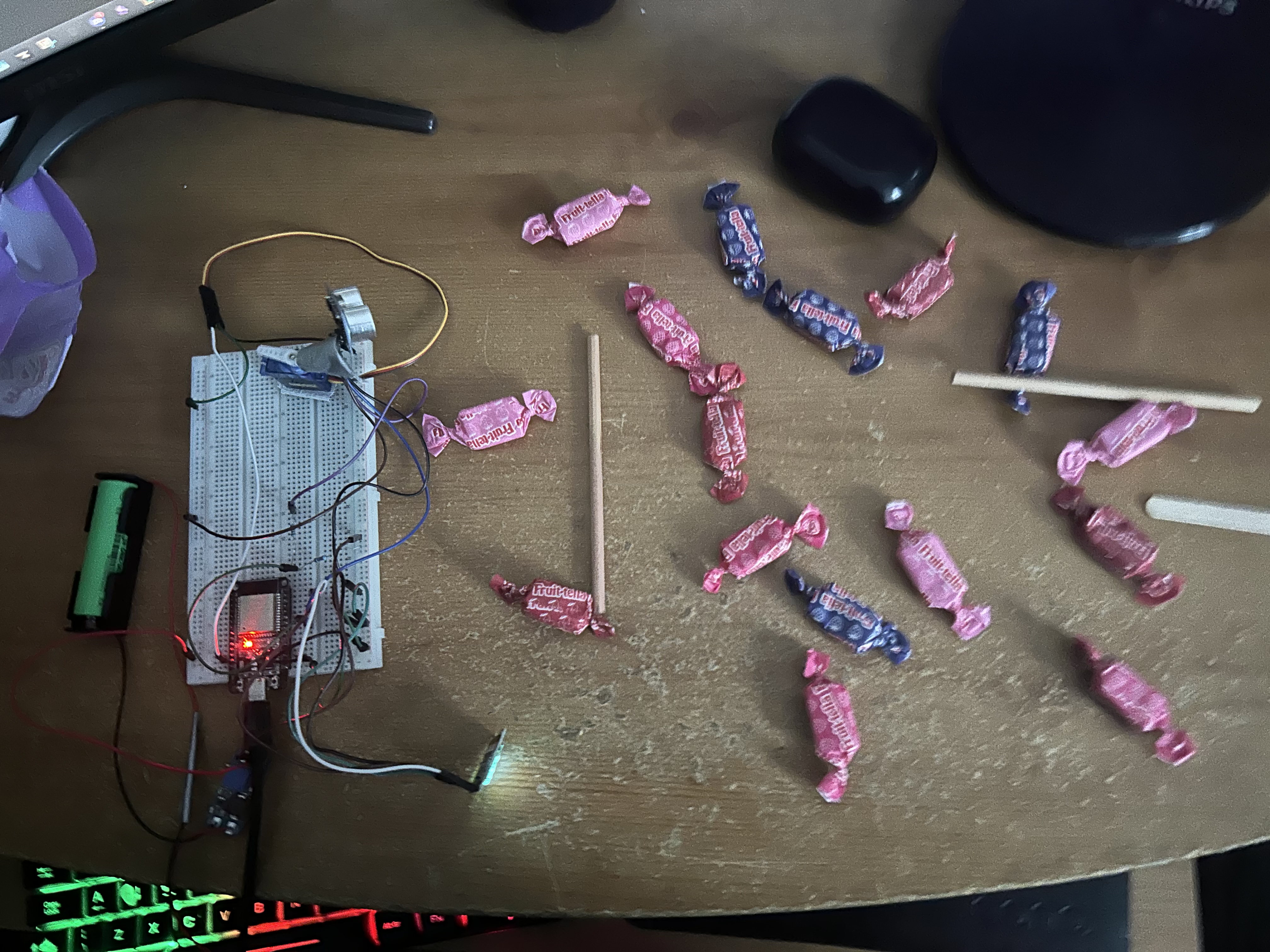
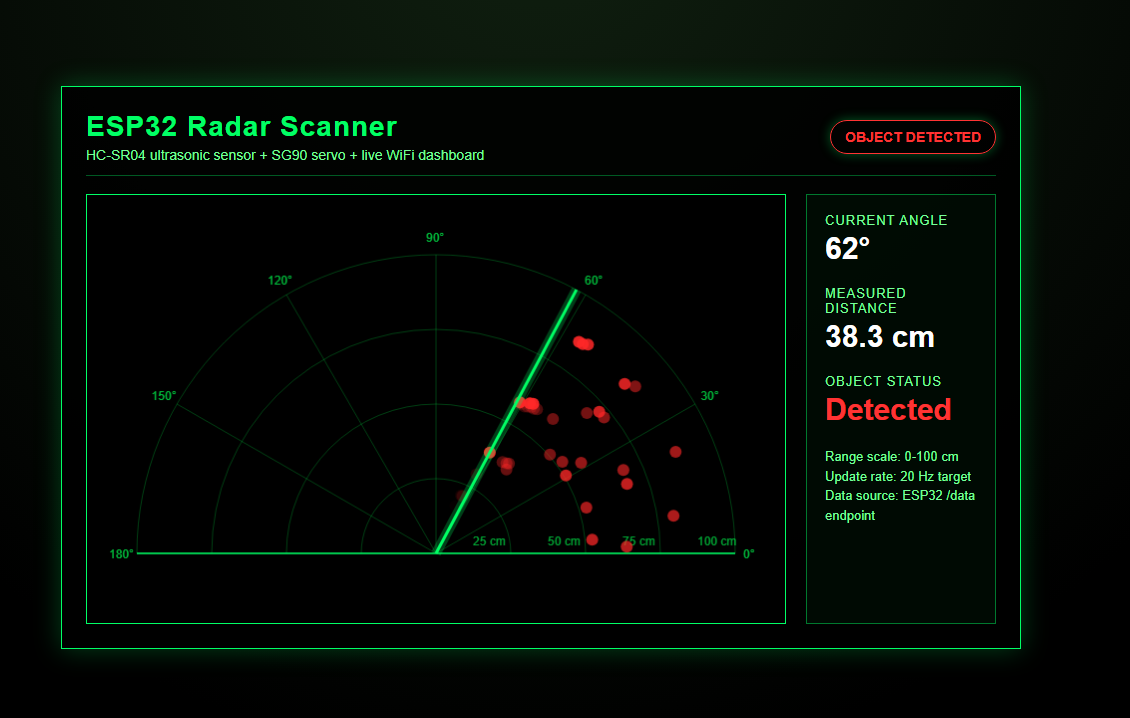
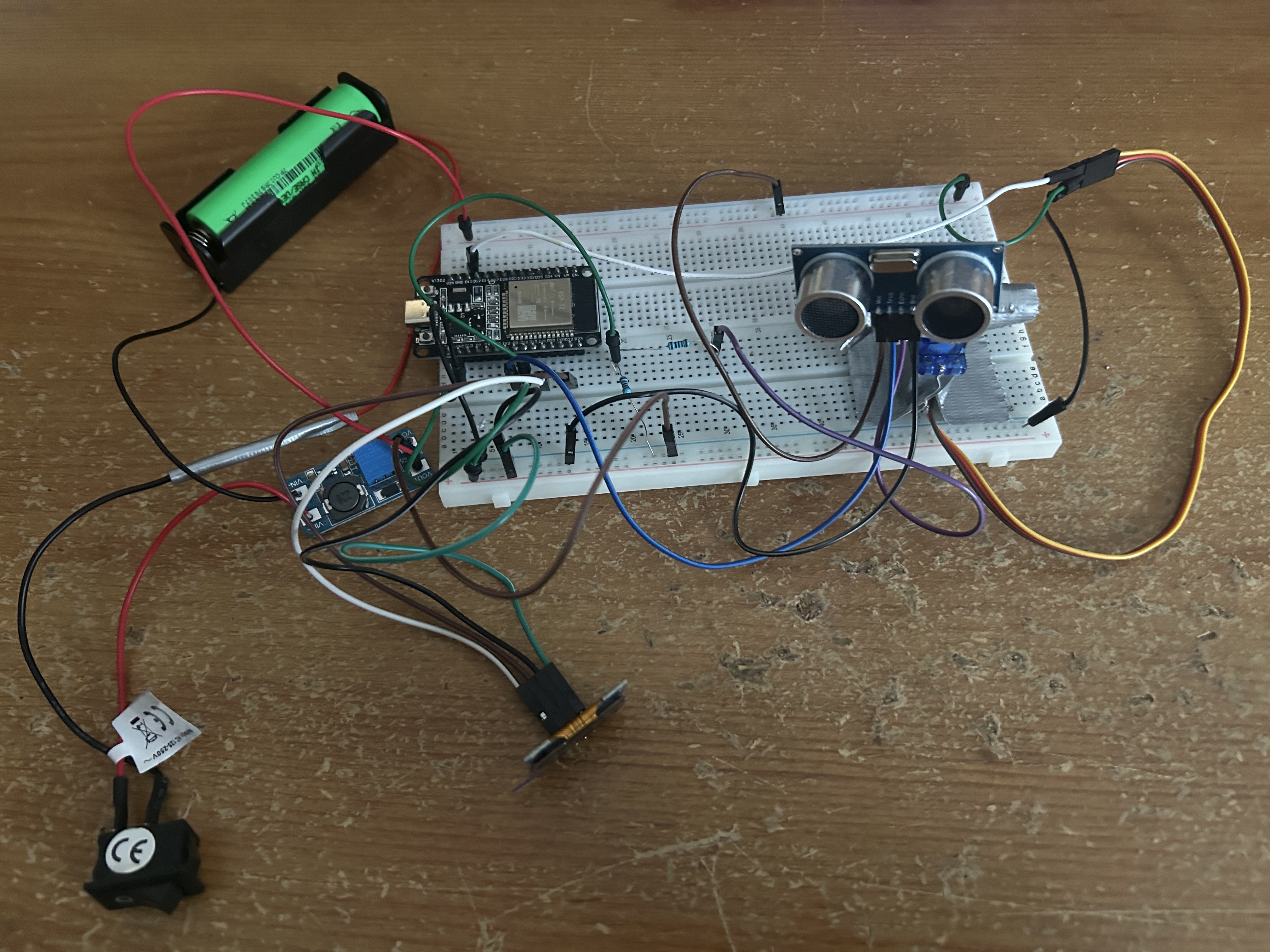
Physical prototype - breadboard, external sensor/servo power rail and temporary sensor mountLive web dashboard - angle, distance and object detection over Wi-Fi
DEMONSTRATEDServo sweep, distance sensing, OLED and Wi-Fi dashboard
01 / PROJECT BRIEF
Objective and demonstrated functions
Develop a low-cost ultrasonic scanner that can rotate a sensor, measure distances at successive commanded angles and present the latest measurement locally and remotely. The system was first exercised in Wokwi, then transferred to a physical breadboard assembly.
0–180°Commanded servo sweep range
0–100 cmDashboard display range for final test area
2 outputsLocal OLED and browser dashboard
2 supply pathsUSB ESP32 and external 5 V sensor/servo rail
Terminology: This is an ultrasonic scanning demonstrator, not a radio-frequency radar. The servo angle is commanded in open loop rather than measured with an angle encoder.
02 / SYSTEM ARCHITECTURE
From sensor sweep to live displays
01Servo sweep
ESP32 commands the SG90 from 0° to 180°, reverses, then repeats.
02Ultrasonic acquisition
The HC-SR04 produces a return pulse used to calculate round-trip distance.
03Local feedback
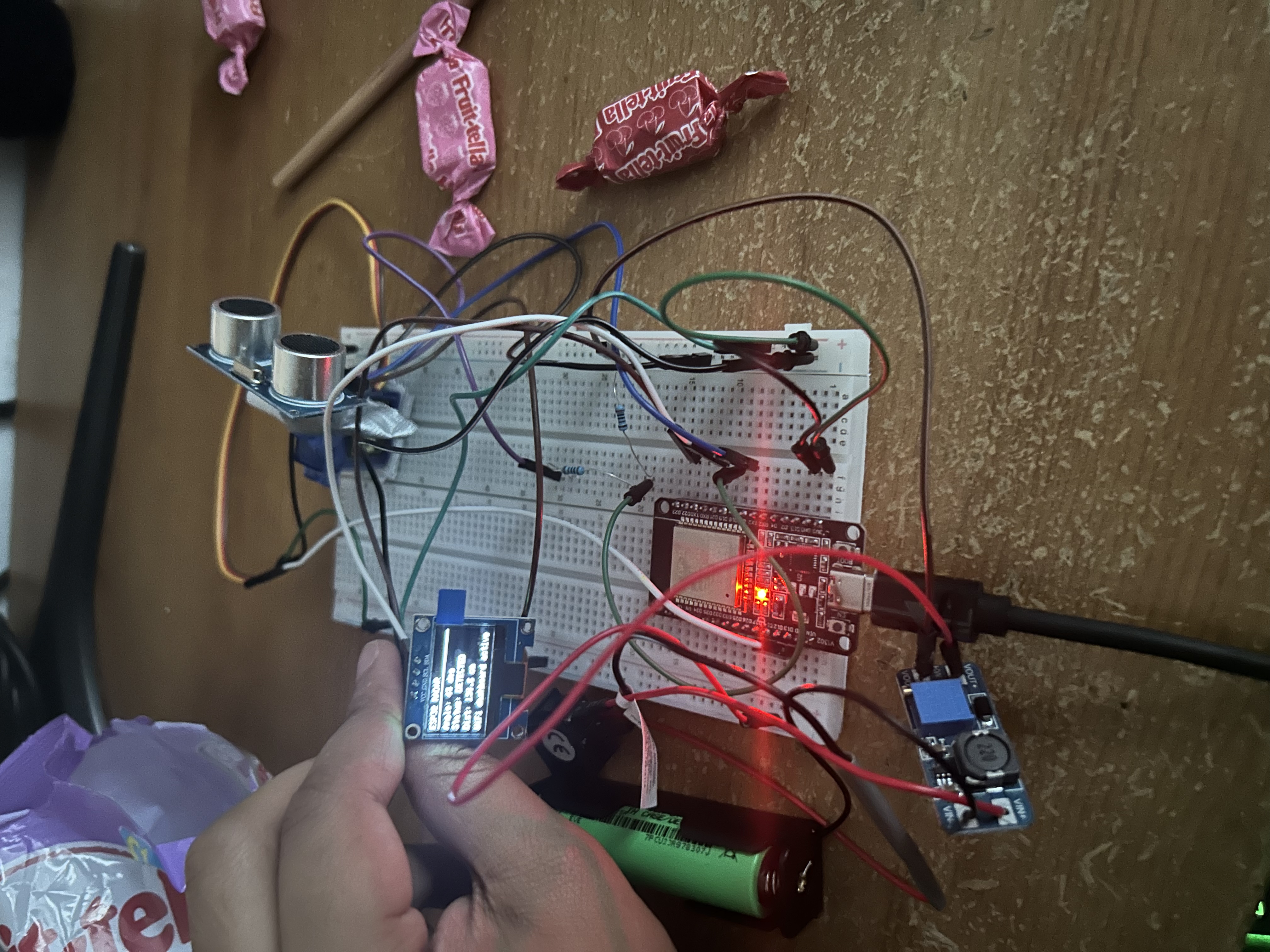
The OLED displays the latest angle, distance and scan/object state.
04Wi-Fi visualization
The ESP32 serves a dashboard; its /data endpoint supplies updated scan values.
The browser repeatedly requests measurement data and redraws the polar display. The displayed angle is the commanded servo position, not independently verified angular feedback.
The division by two accounts for the outward and return travel of the sound pulse.
03 / ENGINEERING DECISIONS
Power, logic levels and testability
01
Dedicated 5 V supply
An 18650 cell with MT3608 boost converter supplied the SG90 and HC-SR04, rather than drawing servo current through the ESP32's 3.3 V rail. The converter output was adjusted to approximately 5 V using a multimeter before powering the hardware.
02
Shared ground reference
The ESP32 was powered through USB while its GPIO signals controlled separately powered devices. Common ground connected the controller and external supply so signal levels had a consistent reference.
03
Echo input protection
The HC-SR04 Echo output operates at 5 V. A 1 kΩ/2 kΩ resistor divider was used before ESP32 GPIO 18, producing approximately 3.33 V for a nominal 5 V high signal.
04
Start with simulation
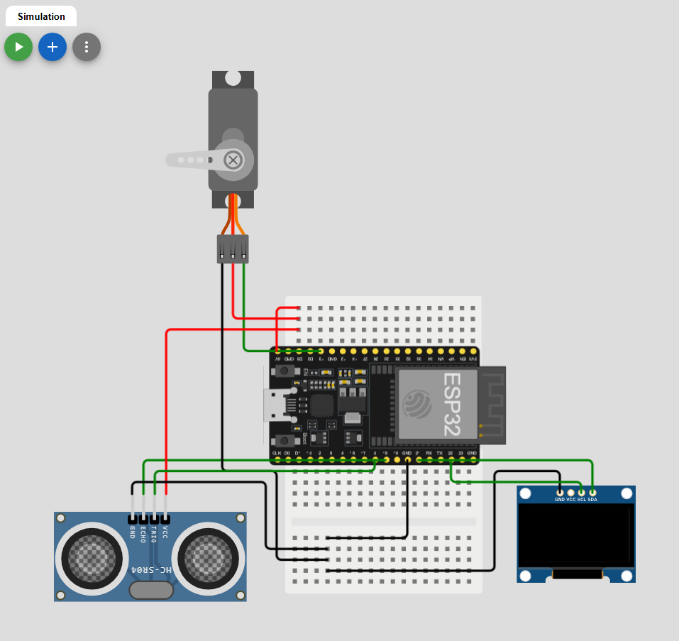
Wokwi enabled testing of sensor interfaces, servo sequencing, OLED layout and web-dashboard behaviour before connecting the real wiring and power supply.
05
Scale the dashboard to the environment
The final browser plot displayed 0–100 cm rather than the earlier 0–400 cm range to suit the available test area. This was a display adjustment, not a verified improvement in sensor resolution.
06
Proof-of-concept mounting
The HC-SR04 used a temporary taped mount while testing. A printed sensor bracket and more compact enclosure were left for a later mechanical revision.
04 / ELECTRICAL DESIGN
Hardware and pin connections
Component
Connection / role
Selection rationale
ESP32 Dev Board
Controller and Wi-Fi web server
Integrated wireless connectivity and sufficient GPIO
HC-SR04 ultrasonic sensor
TRIG GPIO 5 · ECHO GPIO 18 via divider
Low-cost short-range distance acquisition
SG90 servo
Signal GPIO 13 · external 5 V supply
Rotates the lightweight sensing module
0.96-inch I²C OLED
SDA GPIO 21 · SCL GPIO 22 · 3.3 V
Live feedback without a separate browser
MT3608 boost converter
18650 battery to ~5 V rail
Separate sensor/servo power path
1 kΩ / 2 kΩ divider
Echo voltage level shifting
Reduces nominal 5 V Echo pulse to ~3.33 V
Power architecture
ESP32 USB → ESP32 + OLED (3.3 V)
18650 → MT3608 (~5 V) → SG90 + HC-SR04
All subsystem grounds joined; HC-SR04 Echo signal enters the ESP32 through a voltage divider.
Physical wiring and power distributionOLED display during hardware operation
05 / FIRMWARE
Open-loop servo scan and data exchange
The firmware coordinates four functions: servo sweep, ultrasonic measurement, OLED updates and serving live values over Wi-Fi. The dashboard polls the ESP32's /data endpoint and uses the returned values to refresh the display.
Sweep function from the original project documentation:
void sweepRadar() {
  angle += direction;

  if (angle >= 180) direction = -1;
  if (angle <= 0) direction = 1;

  radarServo.write(angle);
  currentDistance = getDistance();
  currentAngle = angle;
}
The function reverses direction at the end of each scan and associates the distance measurement with the latest commanded angle. Mechanical backlash, settling time and timing delays were not independently characterized.
06 / TESTING
Simulation, assembly and results
01
Wokwi prototype
Simulated the ESP32, ultrasonic sensor, servo and OLED to verify the basic wiring and interface logic before assembling the physical circuit.
02
Supply bring-up
Set the MT3608 output to approximately 5 V using a multimeter. A loose power connection was diagnosed after the servo/sensor rail stopped functioning.
03
Physical scan
Observed the SG90 sweeping the sensor, the HC-SR04 responding to objects and the OLED displaying live readings.
04
Web visualization
Connected to the ESP32 dashboard via Wi-Fi and observed live angle, distance and detection updates in the browser.
Original Wokwi circuit simulationBrowser dashboard during real hardware test
Verified scope: The original project documents a functioning servo sweep, ultrasonic response, OLED display and live web dashboard. It does not supply calibrated range-error measurements, angular repeatability statistics, response-time traces or power-consumption logs. These are not claimed.
07 / REFLECTION
Debugging, limitations and next iteration
The main practical issues were electrical rather than firmware-related: correct 5 V delivery, a reliable shared ground, a loose power wire and protecting the 3.3 V ESP32 input from a 5 V Echo signal. Testing in Wokwi reduced uncertainty before energising the breadboard hardware.
Future improvements include replacing the taped sensor mount with a 3D-printed bracket, shortening the wiring, adding a compact enclosure, logging scans, and measuring distance error and servo-angle repeatability. These improvements are planned rather than completed.