Boundary overshoot diagnosed
A strict SOC threshold test uncovered floating-point overshoot. A numerical guard band was introduced in the firmware and reference implementation; all six tested ESP32 boundary cases then passed.
EMBEDDED SYSTEMS / ENERGY / HARDWARE-IN-THE-LOOP · INDEPENDENT PROJECT
A physical ESP32 runs C++ supervisory logic against a simulated 10 kWh battery in Python. A serial hardware-in-the-loop test bench verifies power limiting, state transitions, temperature derating, communication watchdogs and controlled fault recovery.
01 / OBJECTIVE
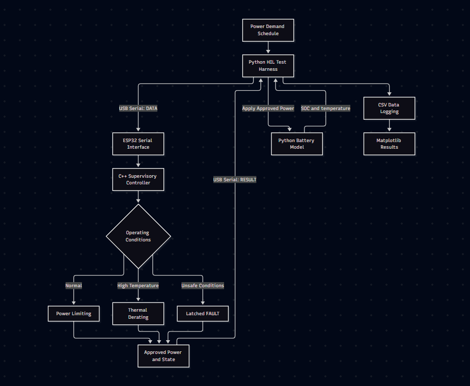
The plant calculates simulated state of charge and battery temperature. Python sends these measurements and requested power over USB serial; the ESP32 independently limits the request and returns approved power, operating state and fault information. Python then applies only the approved power to the next simulation step.
Scope: The battery, sensors, heat generation and cooling are mathematical simulations. The ESP32 hardware executes the controller but does not switch electrical battery power or provide certified battery protection.
02 / DESIGN
The battery uses energy integration with 95% assumed charge and discharge efficiency. A single thermal state tracks internally generated heat and heat transfer to ambient using Cth dT/dt = Q̇gen − UA(T − Tambient).
Integrate SOC, temperature and conversion losses in Python.
Send SOC, temperature, power request and integration interval.
ESP32 clamps power, enforces limits and returns a controller state.
Python checks decisions against reference rules and records results.
| Control feature | Demonstration rule |
|---|---|
| Operating modes | IDLE, CHARGING, DISCHARGING, DERATED, FAULT |
| Power sign | Positive discharge; negative charge |
| Thermal derating | Begins above 40°C, linearly reduces power to 60°C |
| Fault reset | Latched; recent zero-power DATA and recovery temperature below 55°C |
| Watchdog | 3 s without valid data triggers a latched communication fault |
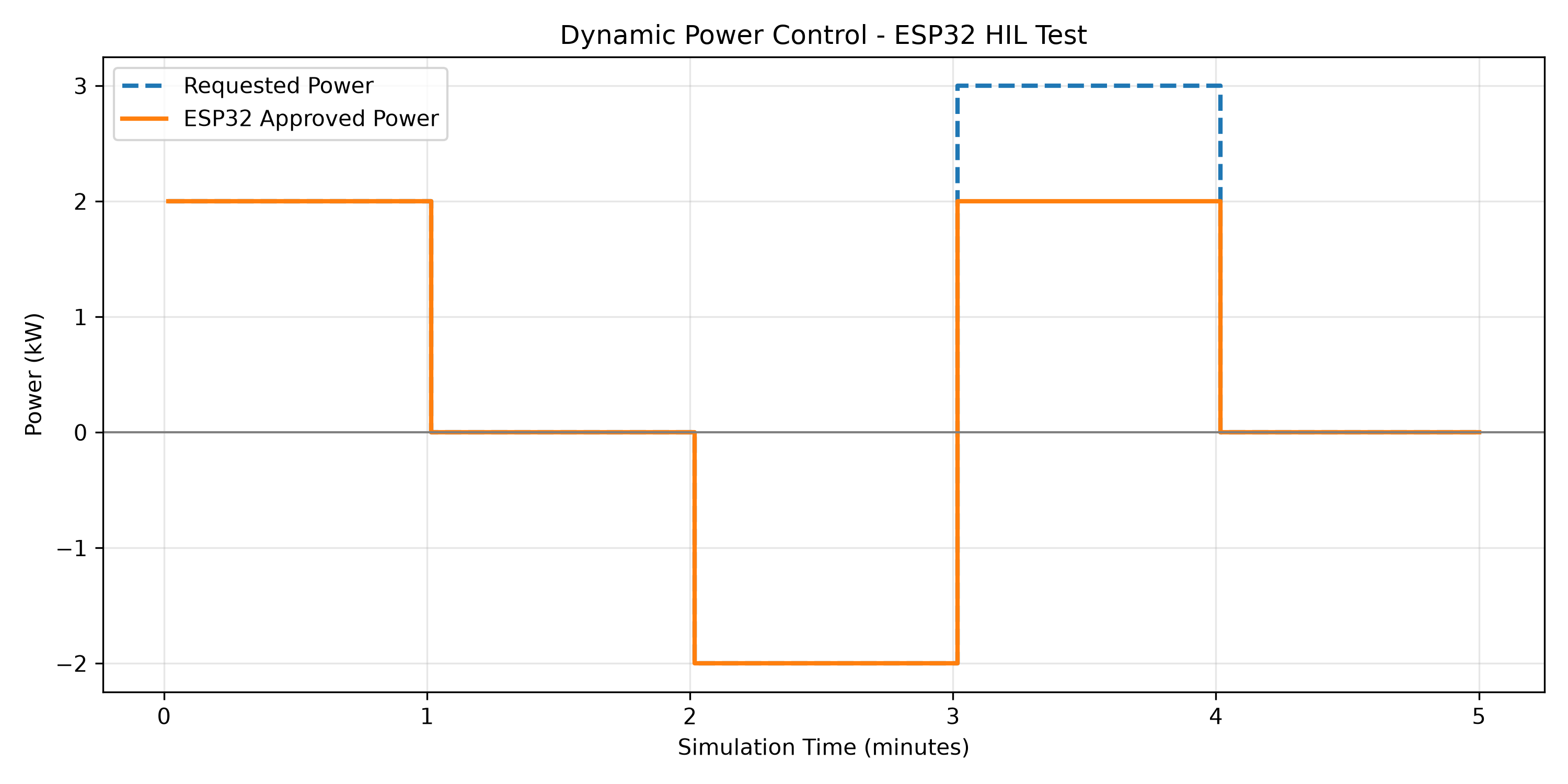
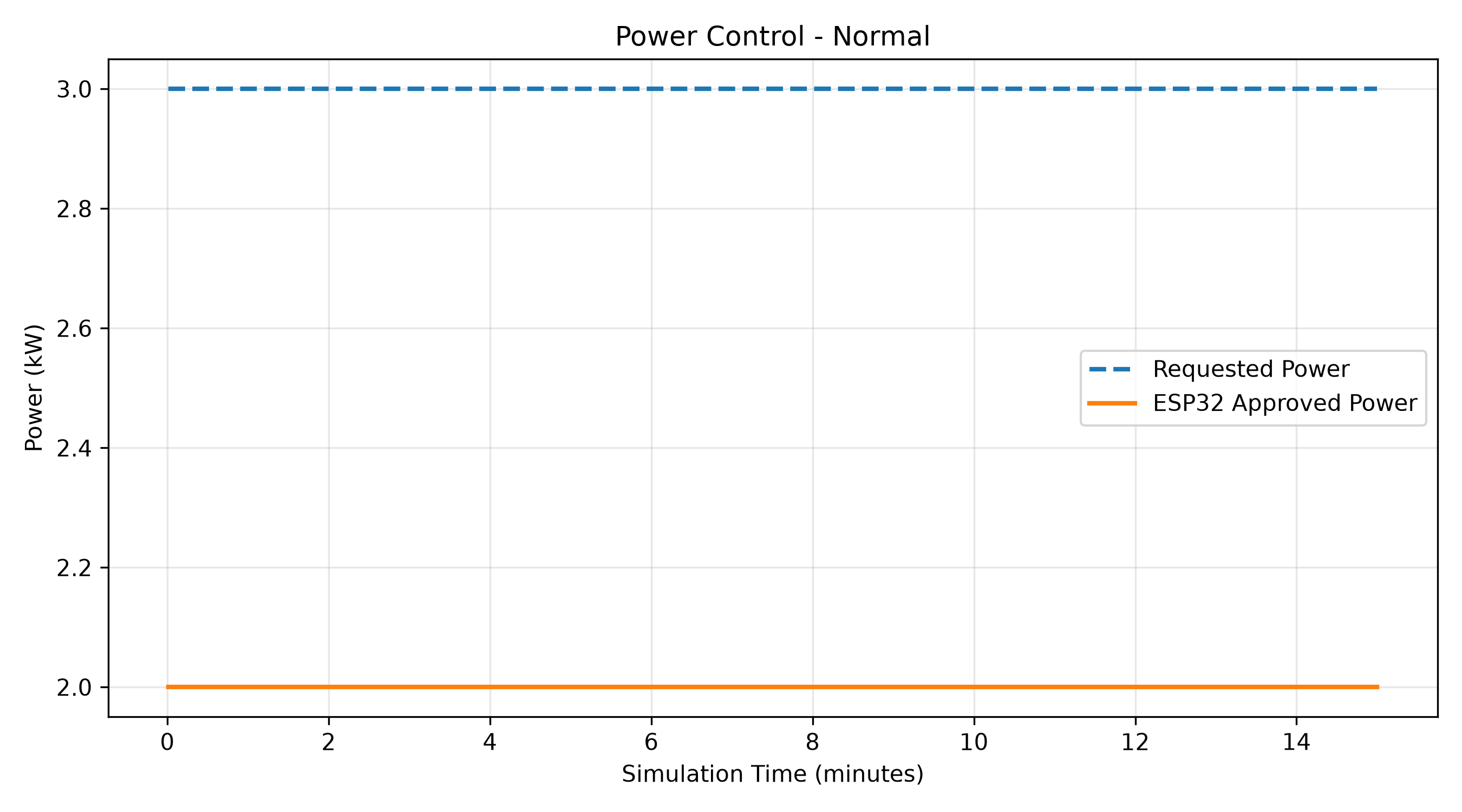
Example exchange: DATA,60,25,3,1 → RESULT,2.000000,DISCHARGING,NONE. The 3 kW request is clamped to the controller's 2 kW discharge limit.
03 / MEASURED TEST OUTPUTS
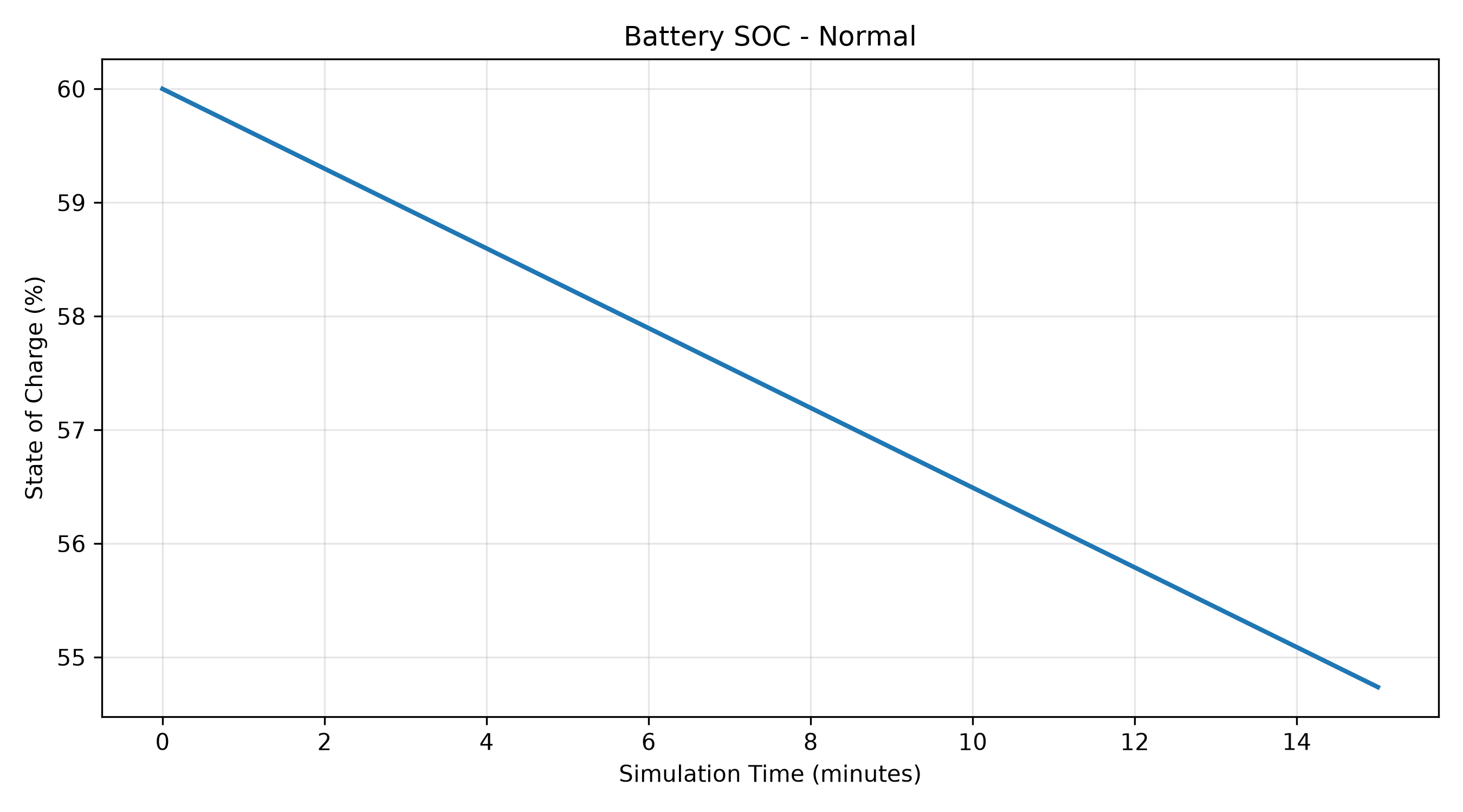
In a 900-second simulated discharge, the physical ESP32 restricted a constant 3 kW request to 2 kW. The battery model integrated SOC from 60% to 54.737%; these values are simulated battery outputs controlled by actual serial firmware decisions.
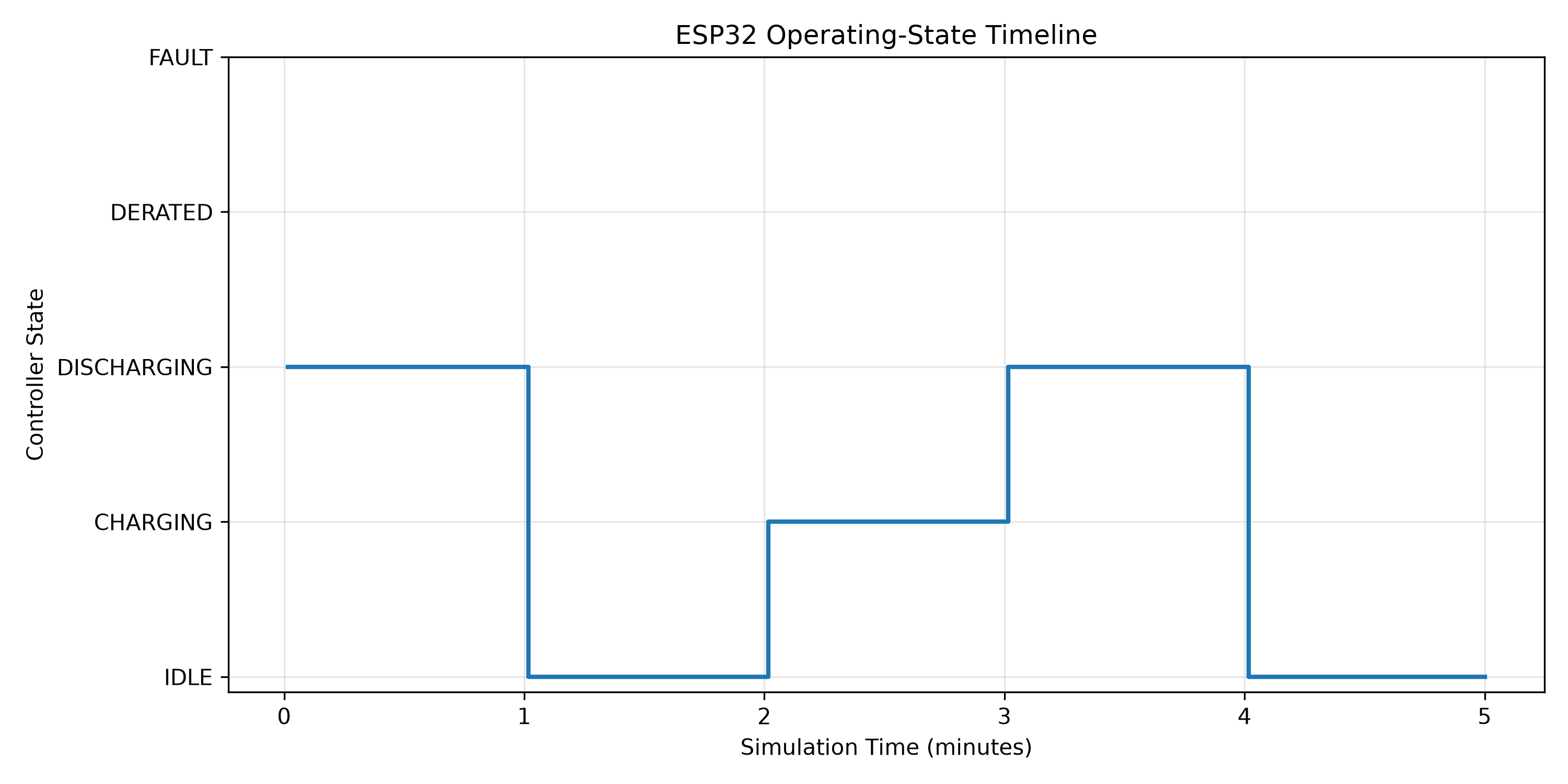
In a separate 300-second scenario, the ESP32 switched between discharging, idle, charging and power-limited discharging. The recorded command responses form the operating-state timeline.
04 / THERMAL CONTROL
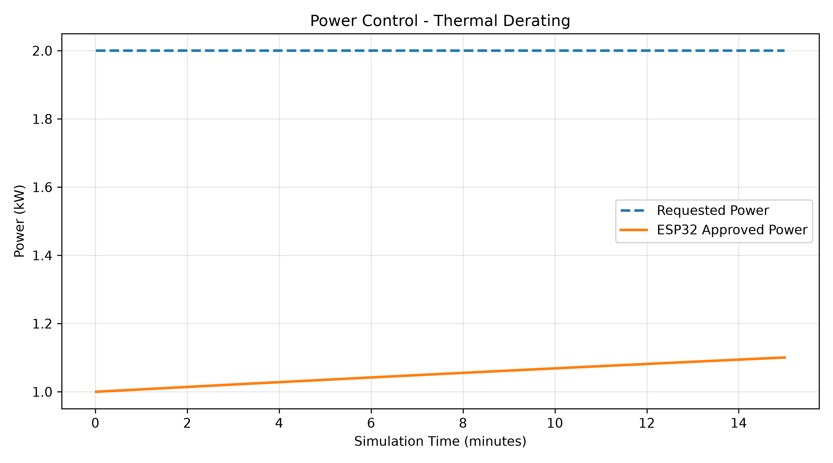
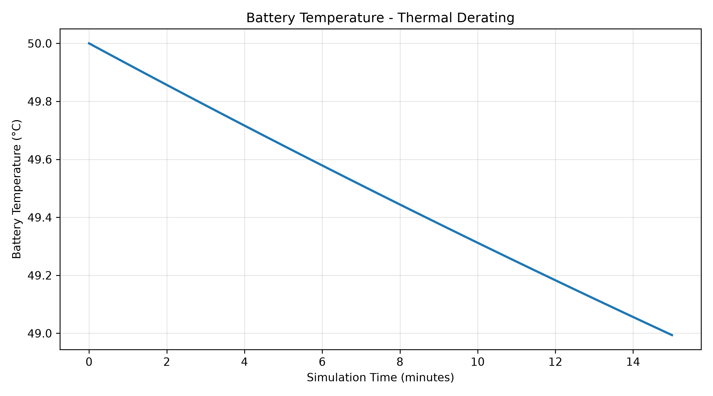
With initial simulated battery temperature of 50°C and ambient temperature of 25°C, approved discharge power began at 1.00 kW. Over 900 simulated seconds, temperature fell to 48.99°C and ESP32-approved power rose to approximately 1.10 kW, consistent with the configured linear derating rule.
05 / VERIFICATION
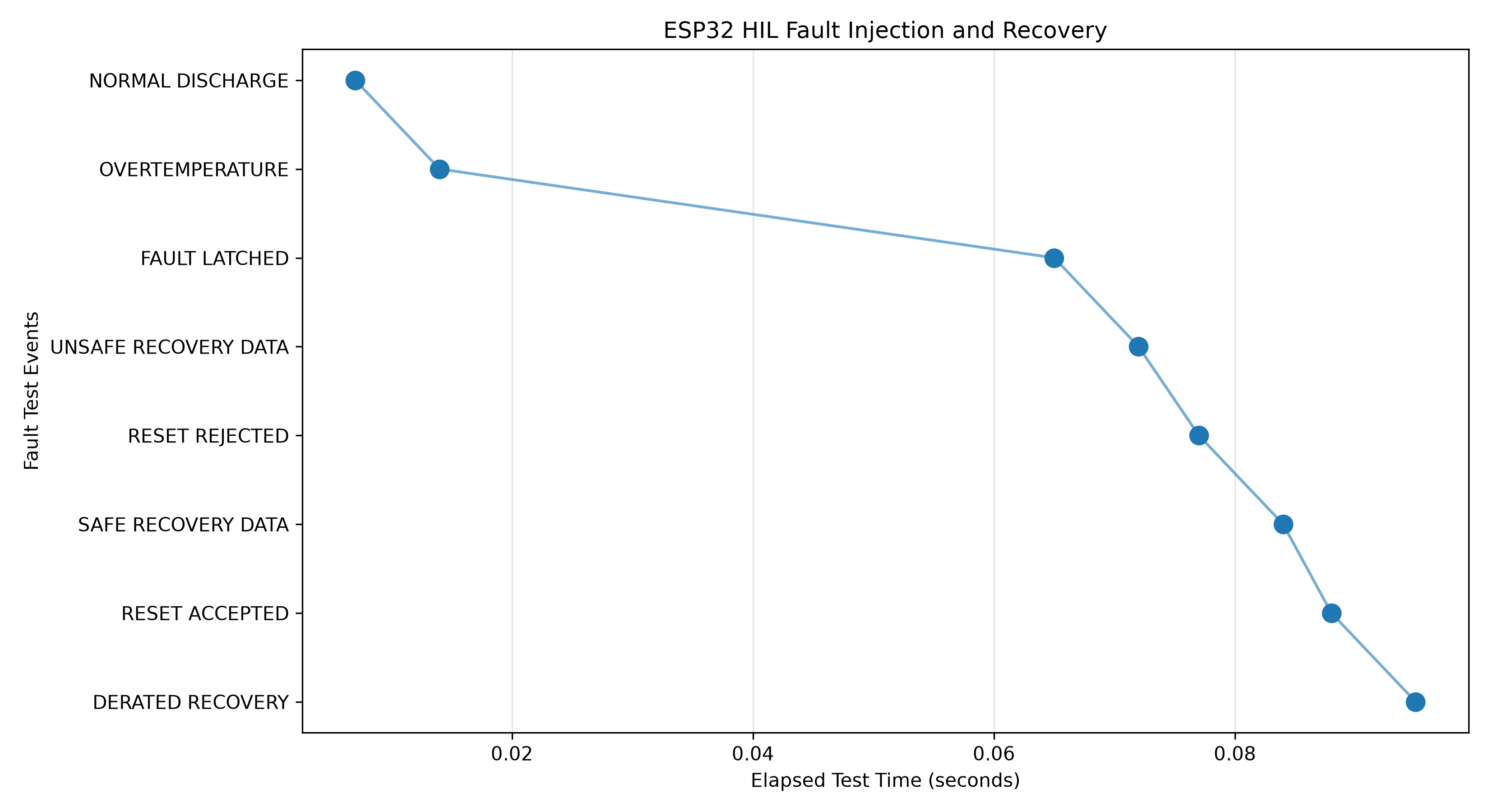
Python automatically supplied invalid sensor inputs, overtemperature measurements and missing communications. The ESP32 latched faults, rejected unsafe resets and resumed derated operation only after accepted recovery inputs.
A strict SOC threshold test uncovered floating-point overshoot. A numerical guard band was introduced in the firmware and reference implementation; all six tested ESP32 boundary cases then passed.
Overtemperature and impossible SOC readings caused zero-power fault responses that persisted after subsequent valid inputs.
A 3-second loss of valid serial messages triggered a fault. Fresh zero-power measurements and an explicit RESET command were required for recovery.
The scripted 100-request run completed in 0.928 seconds of wall-clock time including Python and serial overhead; this is not a guaranteed ESP32 execution time or worst-case response latency.
06 / REFLECTION
The central result is a reproducible separation of plant modelling and embedded supervisory control. The same decision rules were implemented in Python and C++, then checked through a physical serial loop, simulated operating scenarios and deliberate fault injection.
Limitations: The 10 kWh battery and sensors are simulated; no cells, contactors or inverter are connected. Thermal properties are uncalibrated demonstration assumptions. The software watchdog and fault reset are not independent hardware safety mechanisms. These results do not establish industrial battery protection or compliance with safety standards.
Future development: Parameterised controller configuration, firmware timing instrumentation, expanded serial protocol edge-case tests and a representative low-voltage experimental test rig.